Soldering Brass for an Eye Mech
Tips for Soldering Brass: Clean and Strong
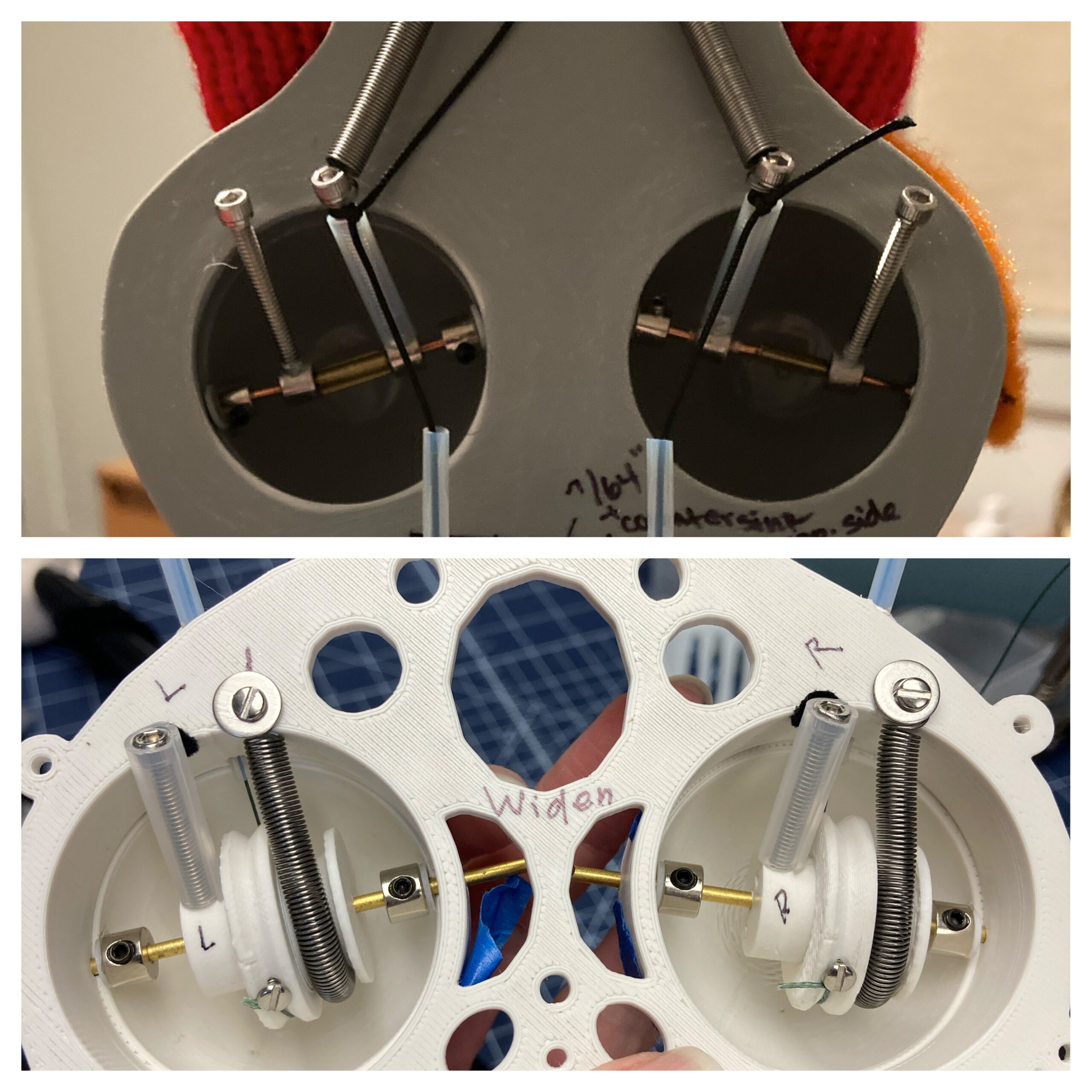
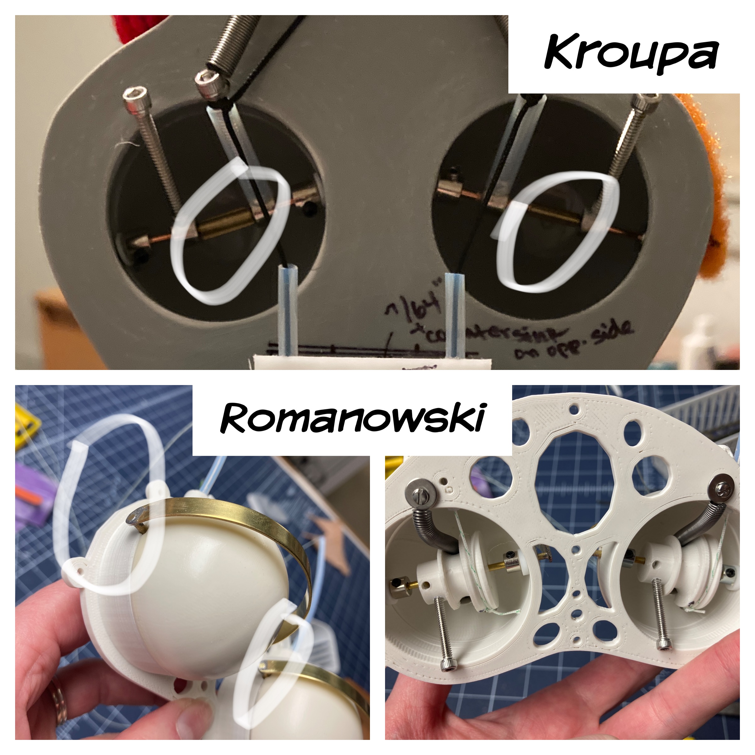
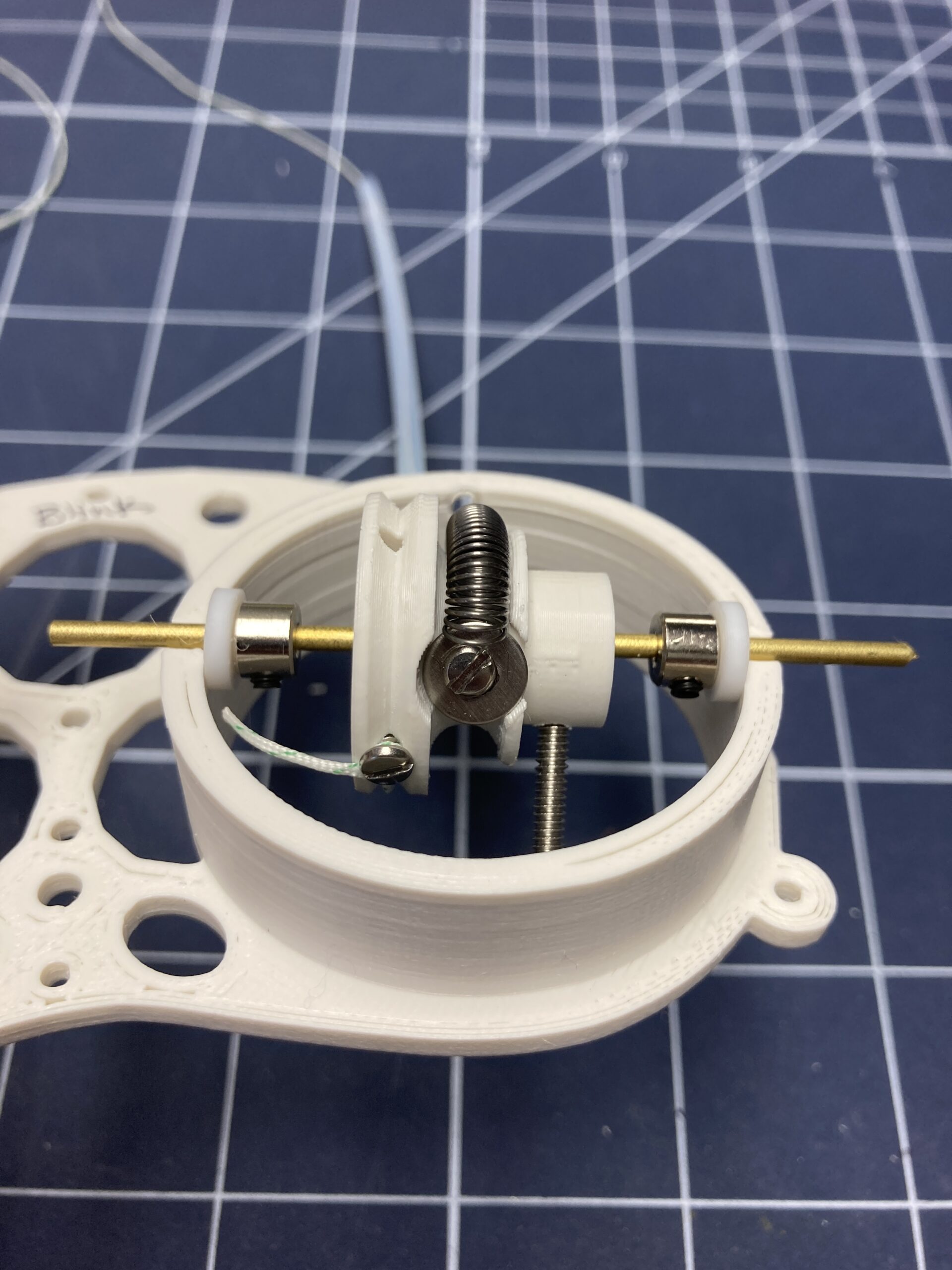
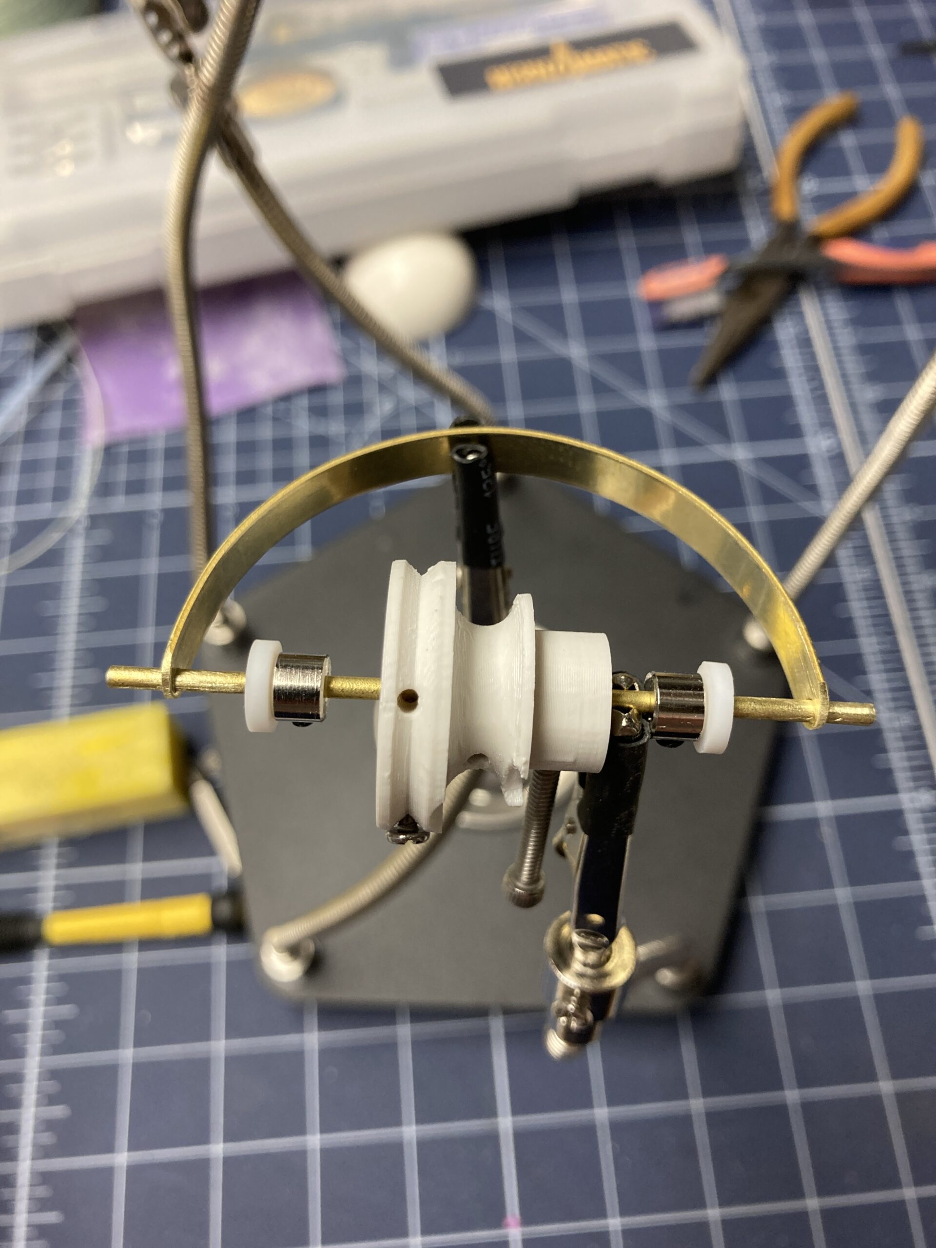
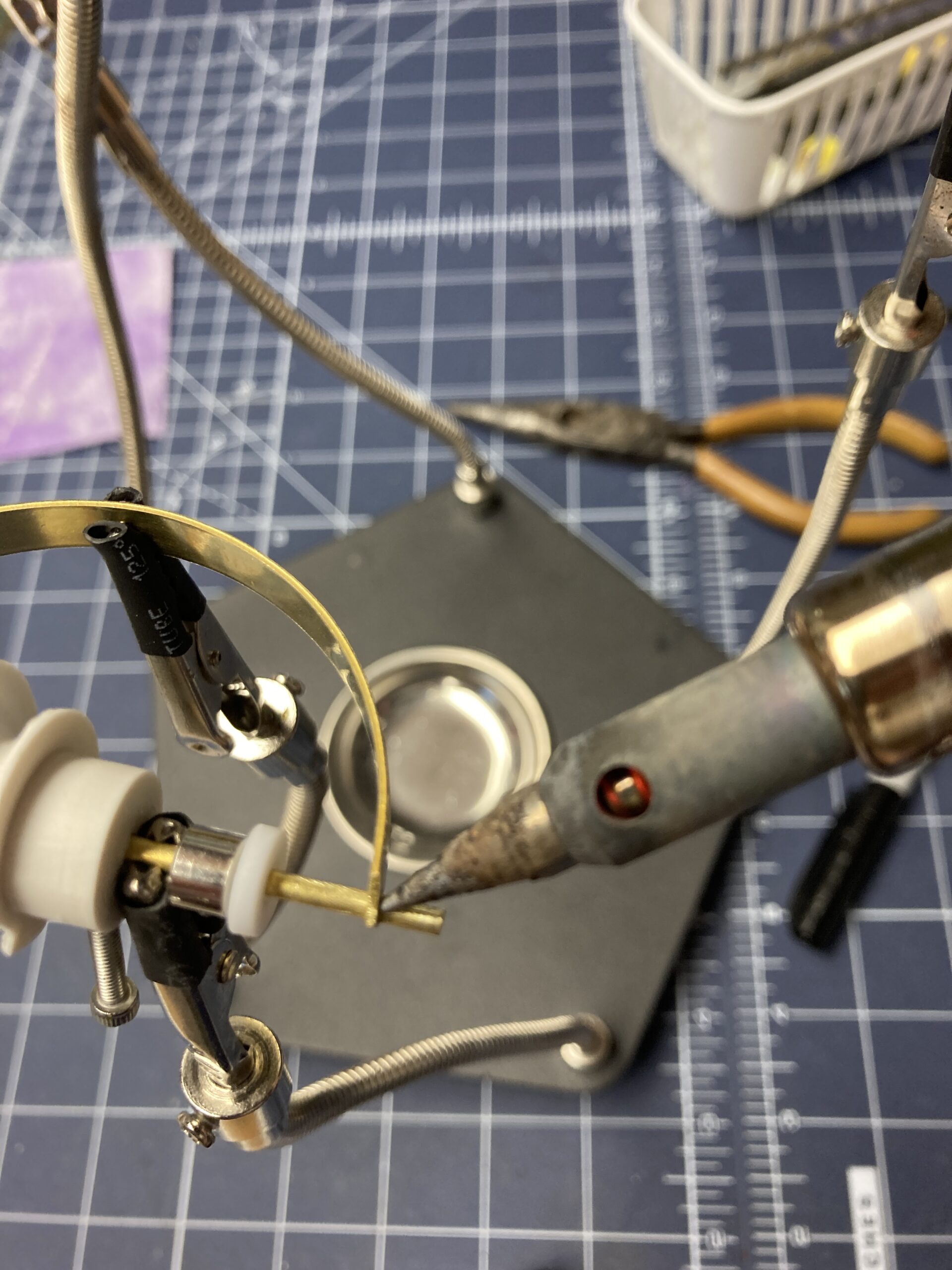
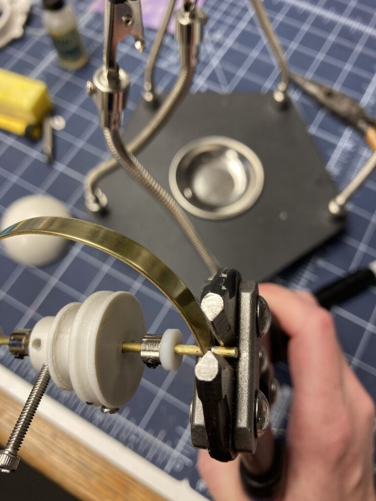
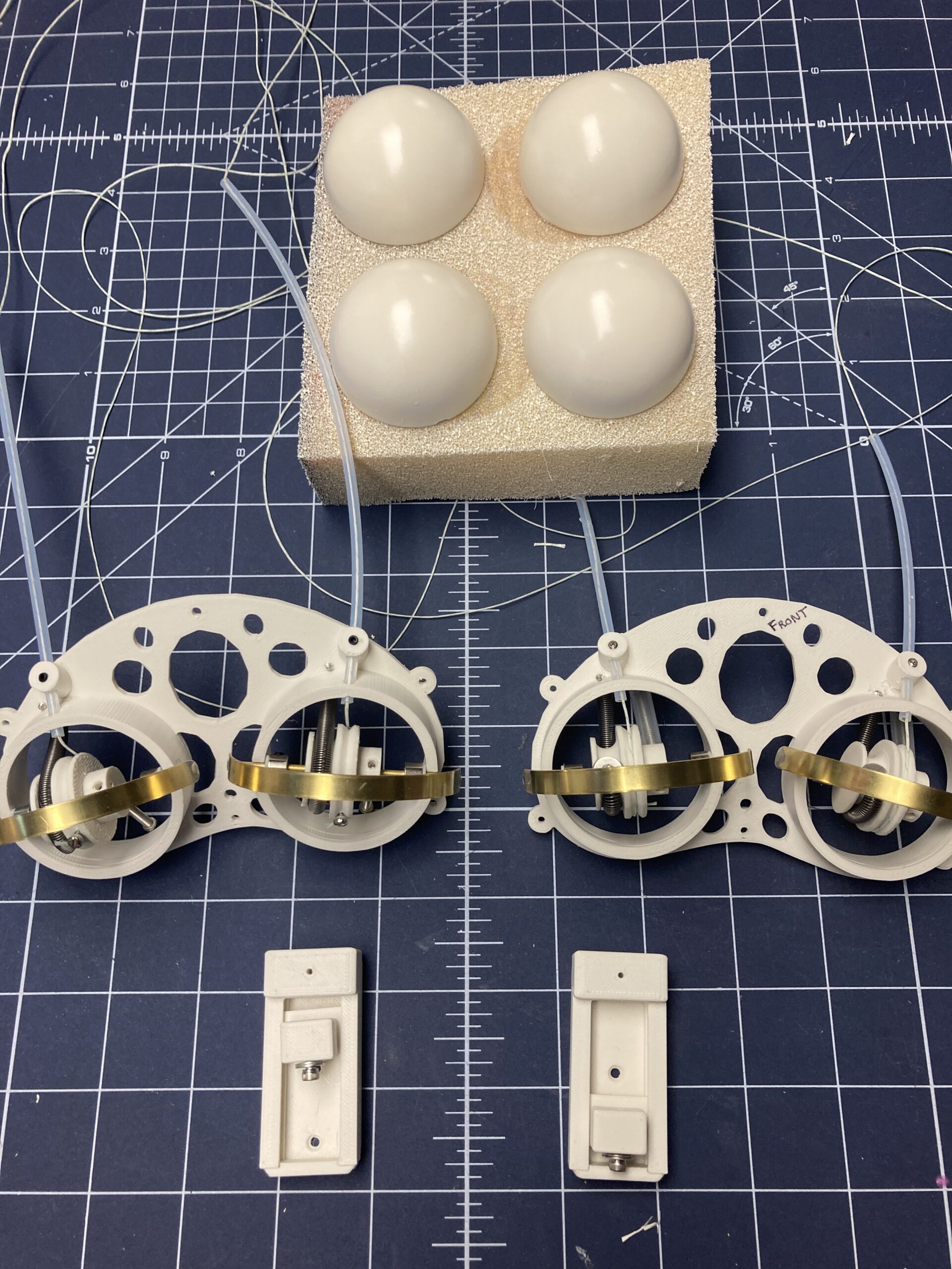
There are multiple ways to make an eye mech. Soldering isn’t required, but I prefer this method. It differs from the method I learned from Jim Kroupa at the O’Neill Puppetry Conference 2025. He used a crimped brass tube to join a wire bent to include both lid and pivot rod. This crimp join is seen in the gray mech between the 2 long 4-40 cap screws (see top photo below). The crimp tool was difficult to find and expensive. The method I’ll describe here is used on the white mech (see bottom photo below). Yet, my first attempts at soldering were not good. They were awkward. The kind folks at my local Rider Hobby store in Grand Rapids gave me some hints.
Why Use the Solder Style Eye Lid?
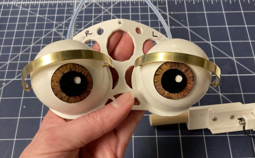
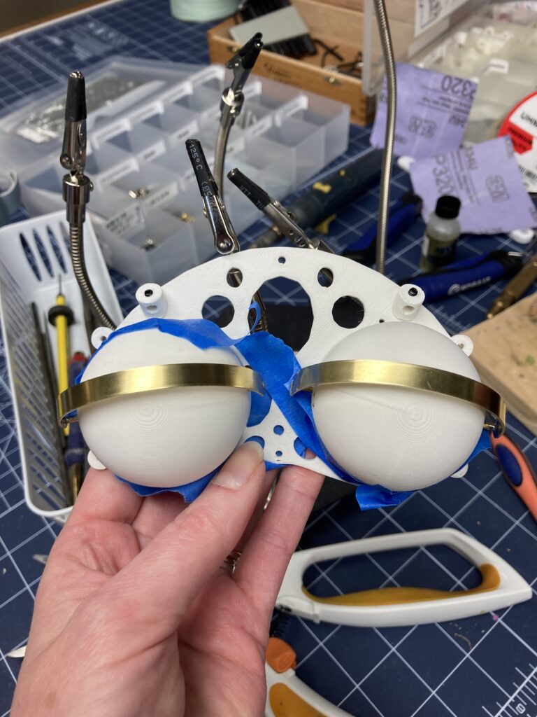
The cylinder design (in the lower image in photo below) is inspired by Pasha Romanowski. It allows for the spring to be housed within the eye dome. Because the coiled length doesn’t anchor far outside the head, the face plate can be smaller. This makes it easier install into a variety of heads. The area where the crimp join lay in Jim Kroupa’s design takes up some space. If the assembly is joined at the eye lid edges, that center space can be used by a cylinder. The cylinder that allows the spring to ride within the eye dome. The control line can exit above or below eye depending on the desired trigger design. If I used the crimp style join, I wouldn’t have room to build my preferred cylinder design on the rod. While the designs are different, they are both effective eye widen mechs. Both can use this soldered brass construction method if desired. Both methods require rod components (washer, shaft collars and cylinder) be added to the rod prior to crimping or soldering. The join area for both designs are circled in white below.
Do I Need a 3D printer?
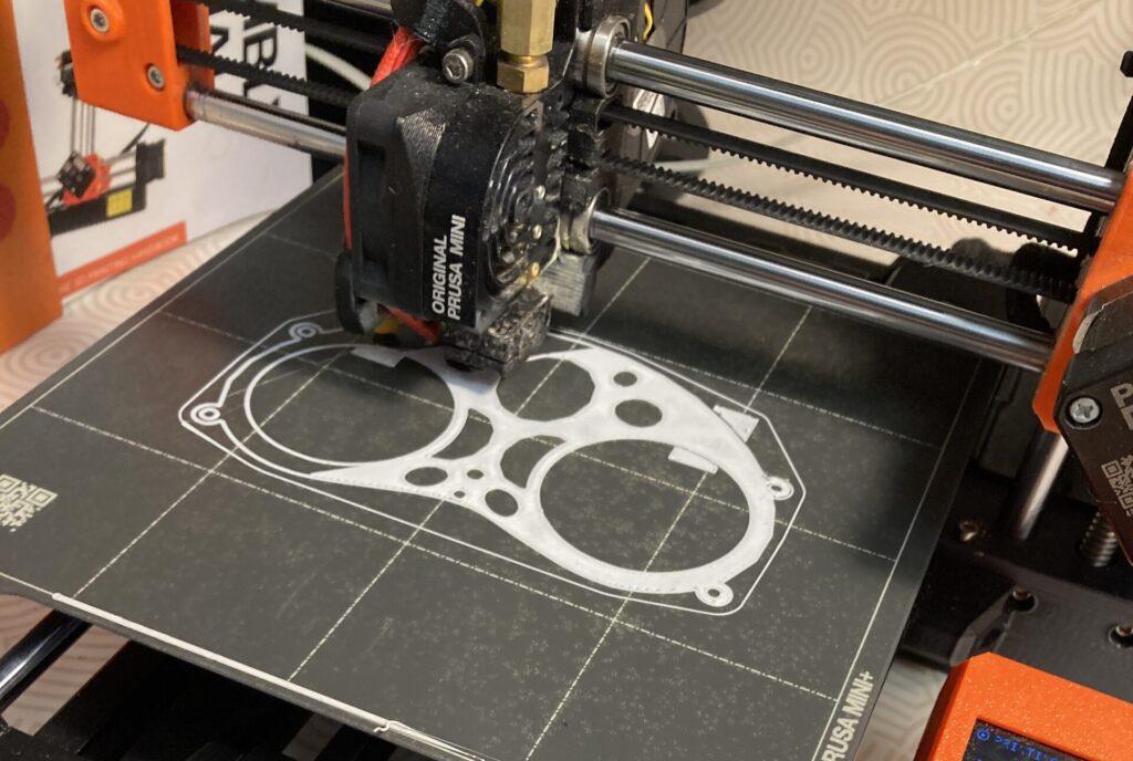
The Romanowski inspired design above includes 3D printed parts versus being hand built in ABS sheet and half domes. All of the white parts in the image above are 3D printed in ASA filament. ASA filament can be tapped for 4-40 machine screws or set screws. I designed my mech in Tinkercad and exported the pieces as .stl files. In my slicer software I increased my perimeter layers to 4 layers deep. This ensures that I have plenty of material to tap for machine screws and set screws. The holes to be tapped are designed into the model. If holes aren’t added to the model prior to printing, holes added by drilling after printing may fall into infill areas that lack enough material to support a solid tap. With that said, I LOVE that this style is more universal. The print time is considerable (1-3 hours for various pieces), but I can do other tasks while my printer makes my pieces. The overall cost for building this mech is a LOT less expensive than hand building from stock ABS components if you already own a 3D printer. If you lack a 3D printer, you can still use the concept of a soldered brass pivot join in the hand built design that Kroupa taught.
Materials
In order to use this method you will need brass pieces. The size can vary depending on the scale of the eye. This eye mech uses K&S 0.081″(2.06mm) brass rod (#8168) and 1/4″ wide by 0.032″ thick brass strip (#8240) from my local Rider hobby store. Amazon also carries it. I also used a soldering iron, flux, helping hands and solder wire for the soldering. Sandpaper, alcohol, heavy duty wire cutters, a drill and drill bit similar in size to your rod (5/64″ or 2mm) are used to cut, drill, clean and sand the brass.
Brass Cutting and Assembly
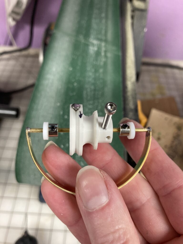
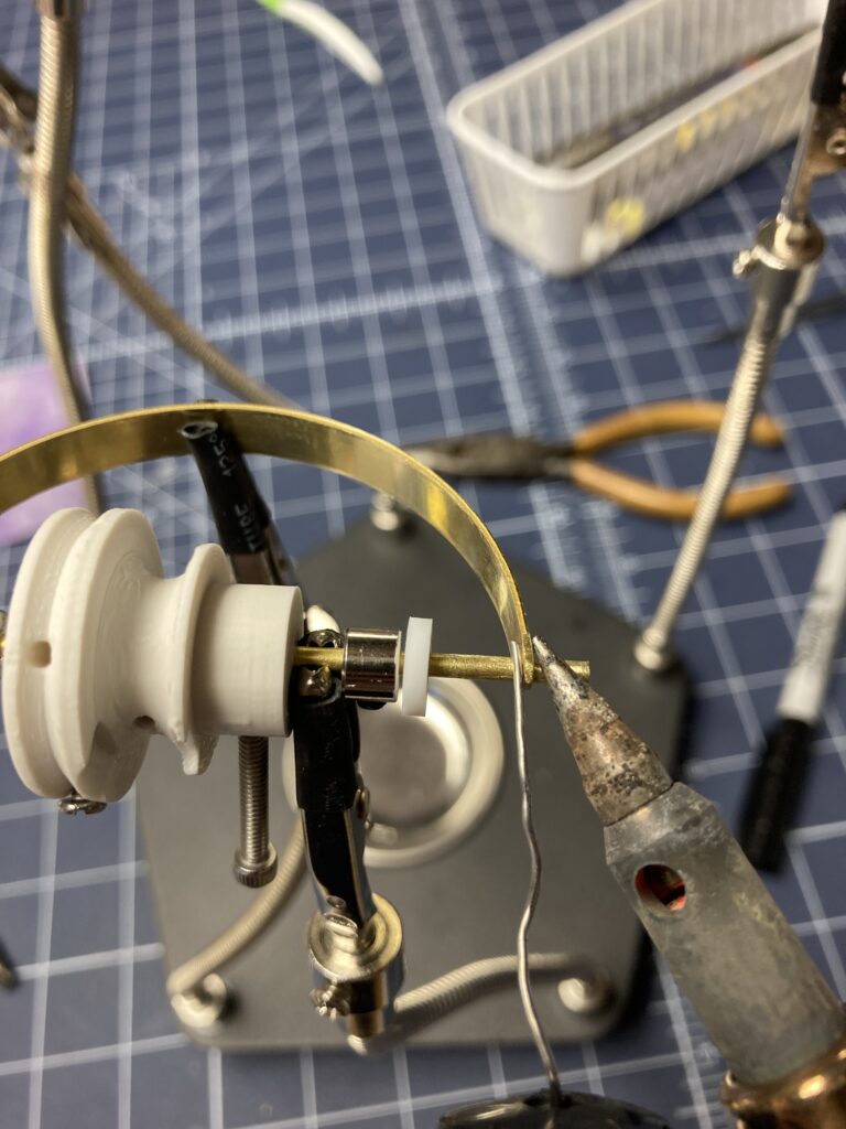
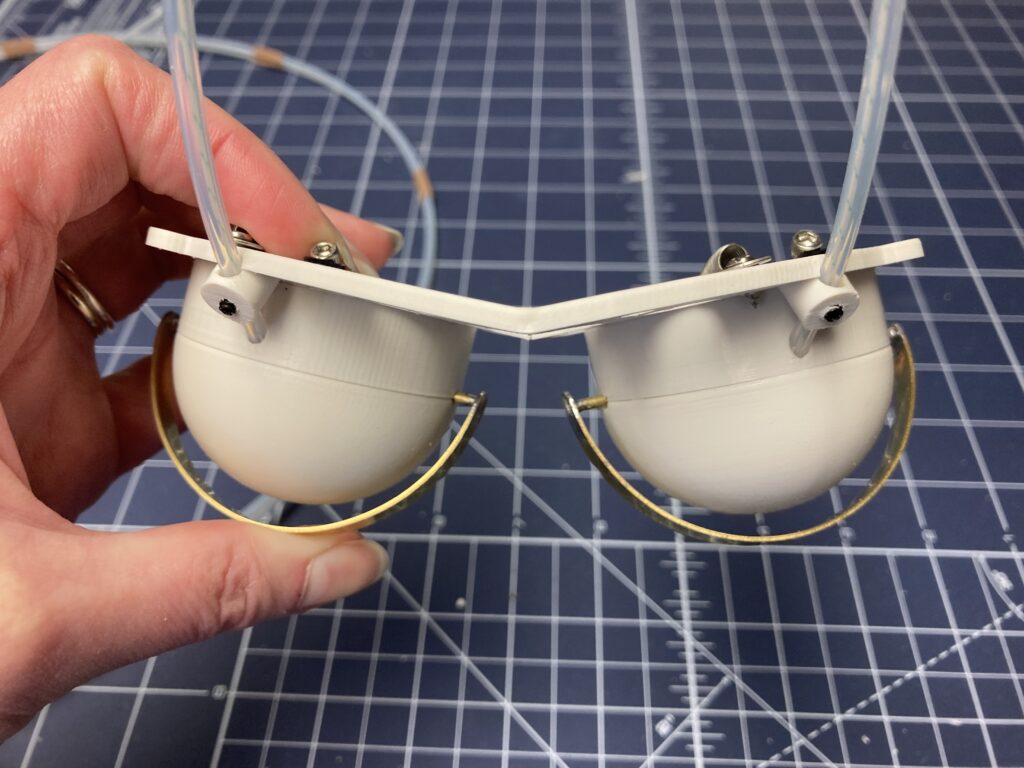
The finished pivot/lid assembly will look like the image above. Before soldering, add the mech components (washers, collars plus the tapped and drilled cylinder) to the rod first. The rod should extend past the eye dome area as seen in the image below. Test the function of the mech before soldering and determine the necessary tolerances between eye dome and brass strip. This gap allows for the fleece covering for the eye lid. In the image below, the cylinder has already been tapped for the 4-40 screw stop, and the stop tightened to the pivot rod. The spring and line have been installed as well, so the line can be pulled and the return action tested.
Metal Clean and Bright
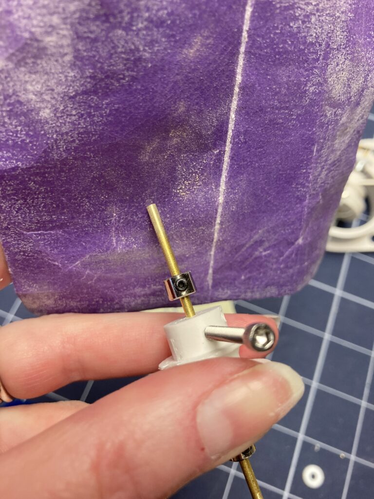
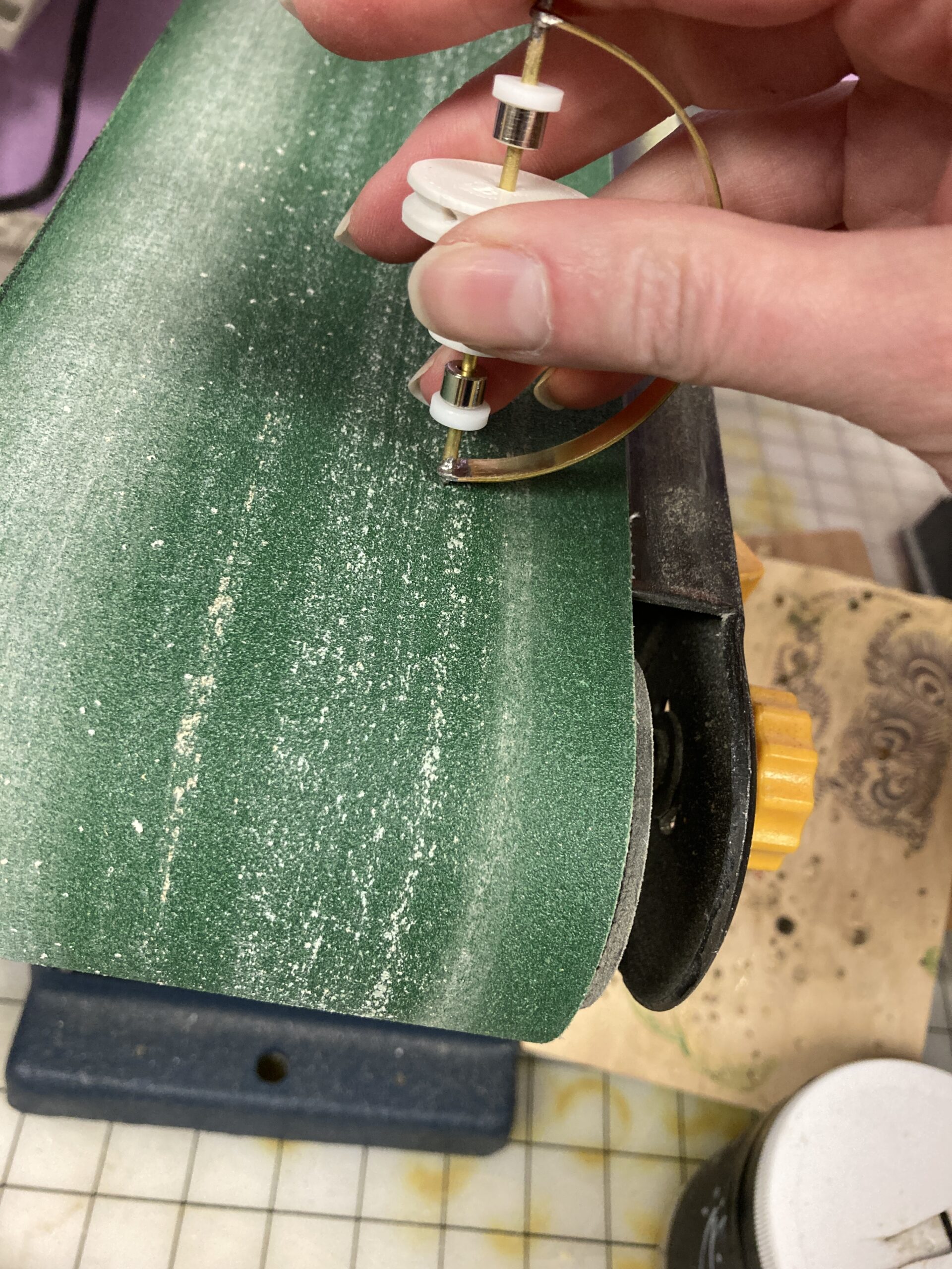
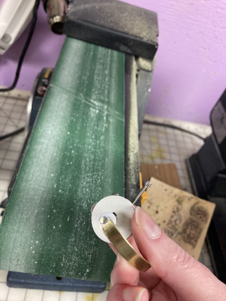
Once the design is tested, bend the brass strip against a pipe fitting that is smaller than your eye dome (1). The brass will spring back some. Test the bent brass against your face plate (2). The gap between eye dome and brass on my model is about 5mm. The brass strip should just slightly extend past the pivot rod ends to allow for holes to be drilled on each end to thread the strip onto the rod. Mark and cut the brass strip with a heavy duty wire/bolt cutter (3). To prevent your drill bit from walking off the brass, mark your pivot hole with a center punch (4). Drill your brass with a drill bit similar in diameter to your rod size (5). Try to get your hole close to the end without going over. In this photo, it’s a tad close (6). After drilling both ends and before moving forward, test to see if your brass strip still has the right tolerance as in image 2. If your brass is too long, you can shorten it. Too short? Recut and try again. Once your brass is drilled and meets your approval, sand the cut edges to a curve on the belt sander if you have one (7). Also sand the flat surfaces near the pivot hole in prep for soldering (8).

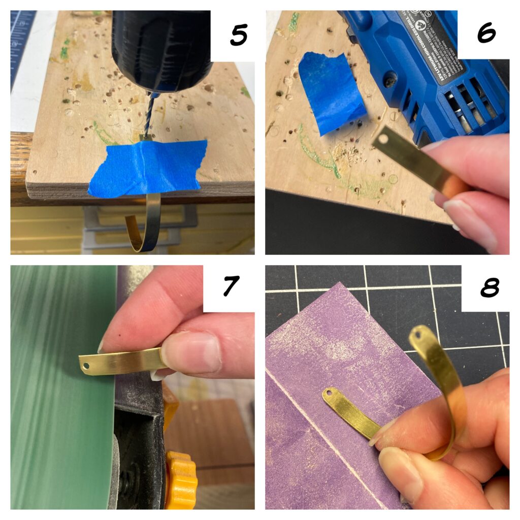
Also sand the ends of the pivot rod in prep for soldering. The advice I got from the folks at Rider Hobby was the phrase “Metal Clean and Bright“. I have it written on my soldering box in thick black Sharpie to remind myself. Use sandpaper or a Dremel tool fit with a small wire wheel to sand all surfaces that will be soldered. This includes both inner and outer sides of the brass strip near the holes because we will solder both sides. I also wiped the sanded surfaces with isopropyl alcohol to remove oils. The rod ends also need to be sanded. Remove the spring and line from the rod, so you can prep the rod with sanding and alcohol as well.
Once the rod and curved lid are prepped, add them to your helping hands assembled and ready to solder.
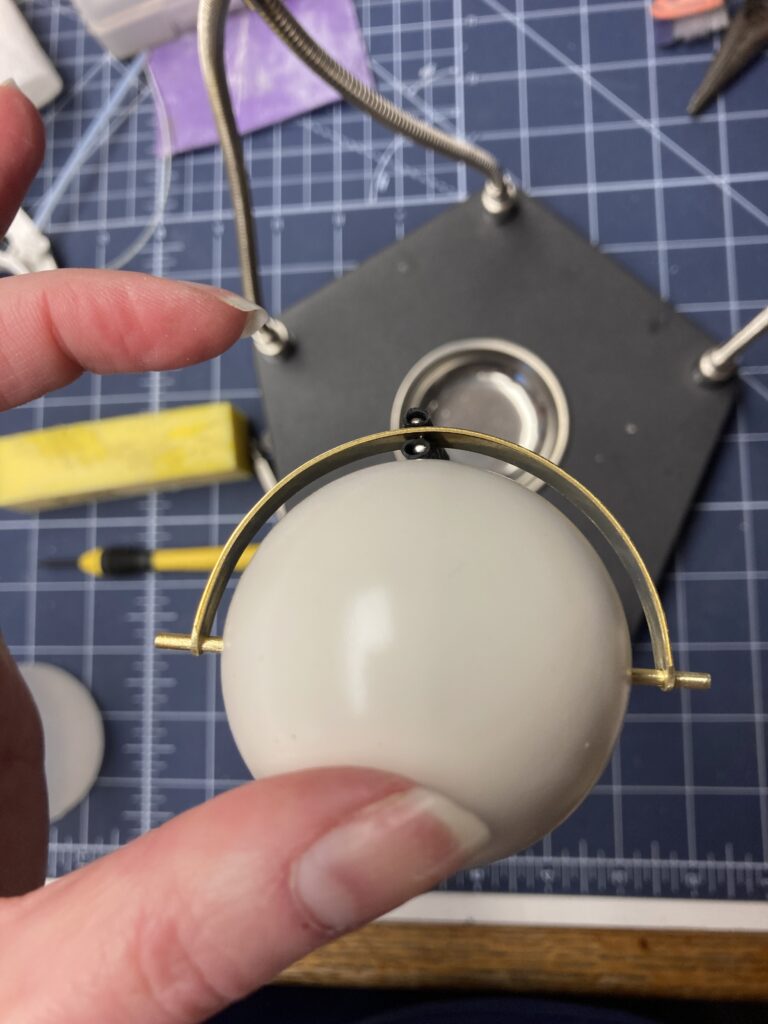
Check your assembly with dome in place a final time to make sure you have enough of a gap to wrap your fleece over the lid. Mine is about 5mm. You can always adjust your collars a bit after soldering, but make sure the brass strip is sitting in the right spot on the rod for soldering.
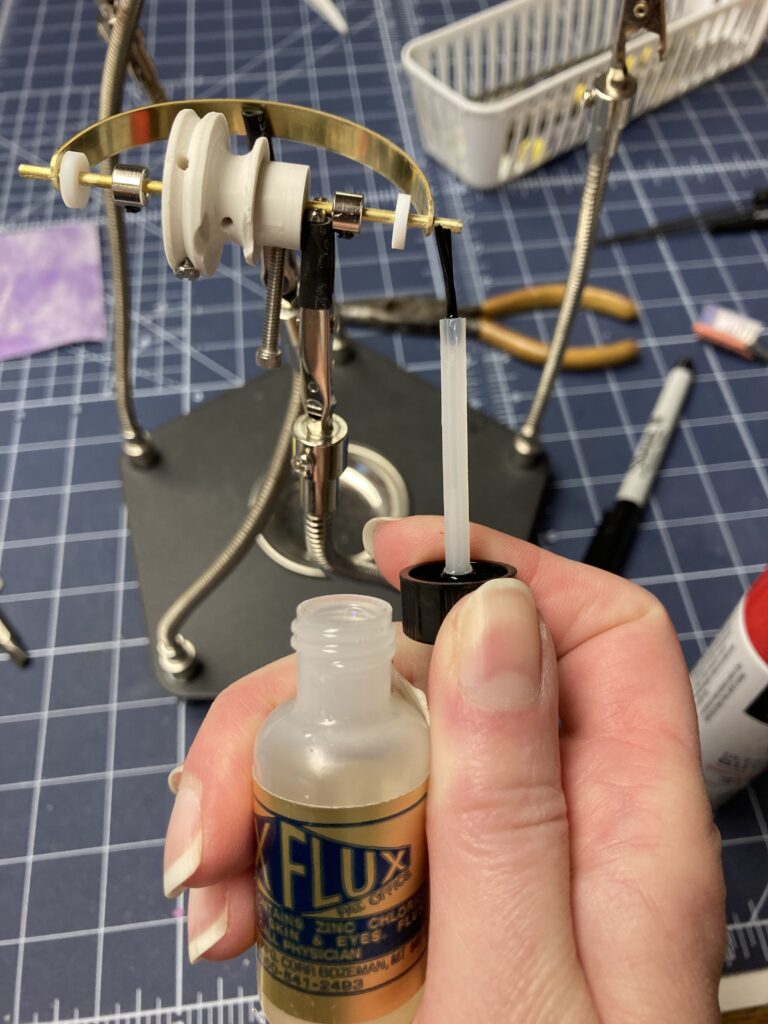
Flux tells the Solder Where to Go
My first attempts at soldering were soldering a steel arm rod to a brass palm plate. I couldn’t get my solder to stick. The results were so messy. For this project, the pieces are both brass, so this will be easier. The key is to make sure the metal surfaces are CLEAN and BRIGHT as described above. Also, use FLUX to show the solder were to go. Now that your assembly is held still in the soldering helping hands, apply the flux to the circumference of the rod. Apply to both inner and outer circumferences of the rod where it passes through brass lid.
Soldering
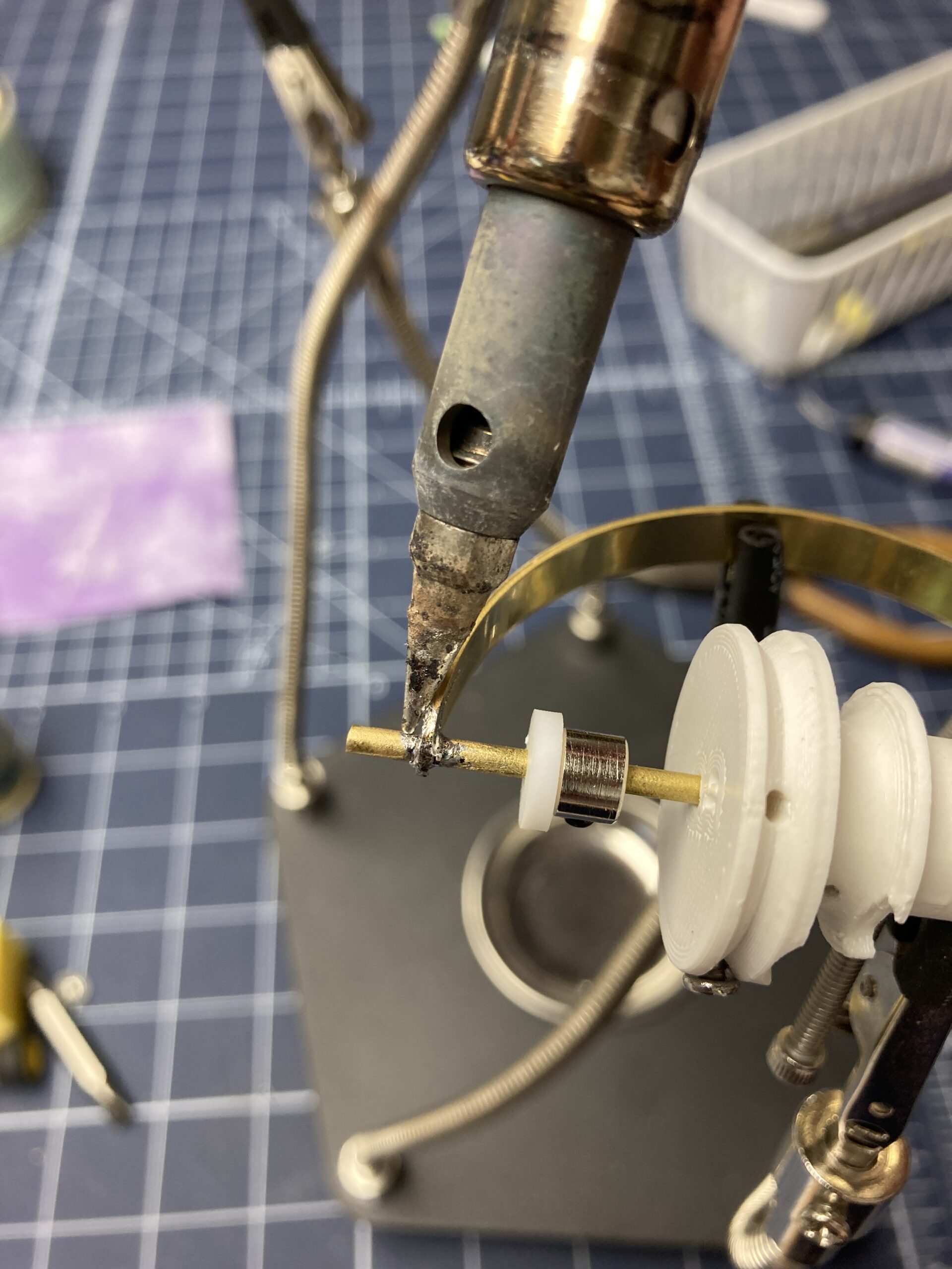
I’m definitely a newbie to soldering, but my results with soldering two brass pieces have been a LOT more successful than soldering steel to brass for arm rod assemblies. If you have been having similar issues, swap your pivot rod to brass, so both parts are brass. Heat up your metal near the join area with the soldering tip. My soldering iron usually has some of leftover solder on it, so I it’s tinned already. Add soldering wire near the solder iron tip and once it starts to melt, spread it with the tip so it covers the entire area around the pivot hole on the outer side. Repeat for the inner side of the pivot hole. Repeat this process on the inner and outer sides of the other side of the lid.
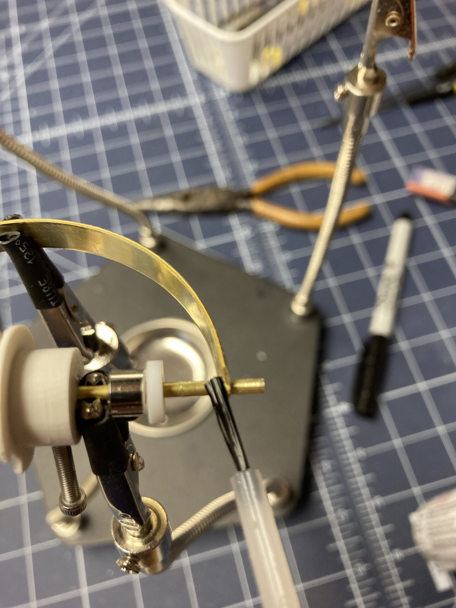
Test. Trim. Sand.
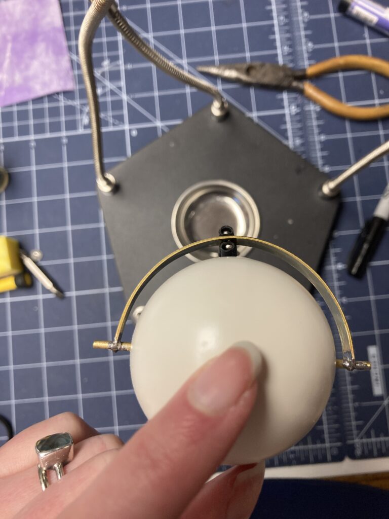
Check the finish soldering with the eye dome. See that the tolerances for the gap and the curves look right. Trim the rod down with the bolt/wire cutters. Sand the ends close to the join.
Final tips
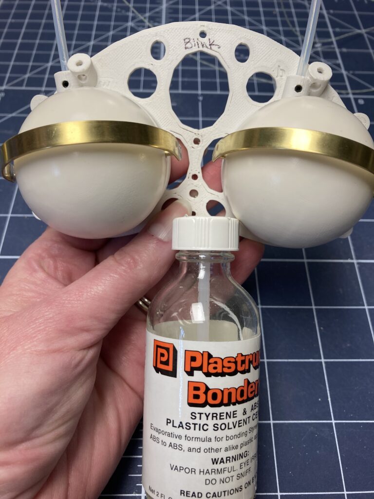
Now that the soldering is done, reassemble the the mech with springs and line in place. Make final adjustments on collars and cylinders before gluing the eye domes down. It’s also important to prep the eye domes in advance before gluing. Sand, paint and seal the domes ahead of time. Ensure that the pivot holes in the faceplate and eye domes are large enough to allow smooth movement. Tape the domes in place and test before final gluing. I used Plastruct Bondene to melt my 3D printed ASA components (domes and faceplate) together. It also works on ABS. (Use care with this product. Avoid getting it on your skin.) If you normally 3D print in PLA, this material does not tap properly or glue with Plastruct Bondene. I don’t recommend it. If you are new to 3D printing in ABS or ASA, it is a little more finicky. It prints better within an enclosure. It’s also smelly, so I vent my enclosure to the outside. See my blog post on finishing 3D prints to see a photo of my ventilation system. It vents contact cement fumes and spray paint fumes and overspray. It also vents my 3D printer enclosure. The two boxes are seperated by dust gates to prevent paint spray from landing on my 3D printer. https://www.lapuppets.com/finishing-3d-prints/ As always, use safety. Besides standard power tool safety, there are respiratory concerns with ASA and ABS from both fumes and sanding dust. The Plastruct Bondene can absorb through your skin and harm your liver. Looks like I should be using that in my vented cabinet with gloves on according to the internet. See my blog post on sanding ABS/ASA prints for safely. That one has already caused me lung problems, so I created a downdraft table as described in this blog post. https://www.lapuppets.com/homemade-downdraft-sanding-station-for-sanding-3d-prints/
Also, the face plate is bent with a heat gun sometimes after printing. This allows the mech to better conform to the rounded shape of the puppet head. This might be riskier to do with the mech fully assembled, although I’ve done it both ways..before and after mech assembly. The advantage of doing it after full assembly is that assembly and testing is a little easier when the faceplate is flat.
Dog Puppet with Eye Widen
Ending this blog post with scary safety concerns is NO FUN! Puppets are SO FUN, so let’s see this mech in a puppet. See my dog Ollie below. Happy Building!
