Be the First to Discover My Dowel Drilling Hack
Dowel Rod Blow Outs
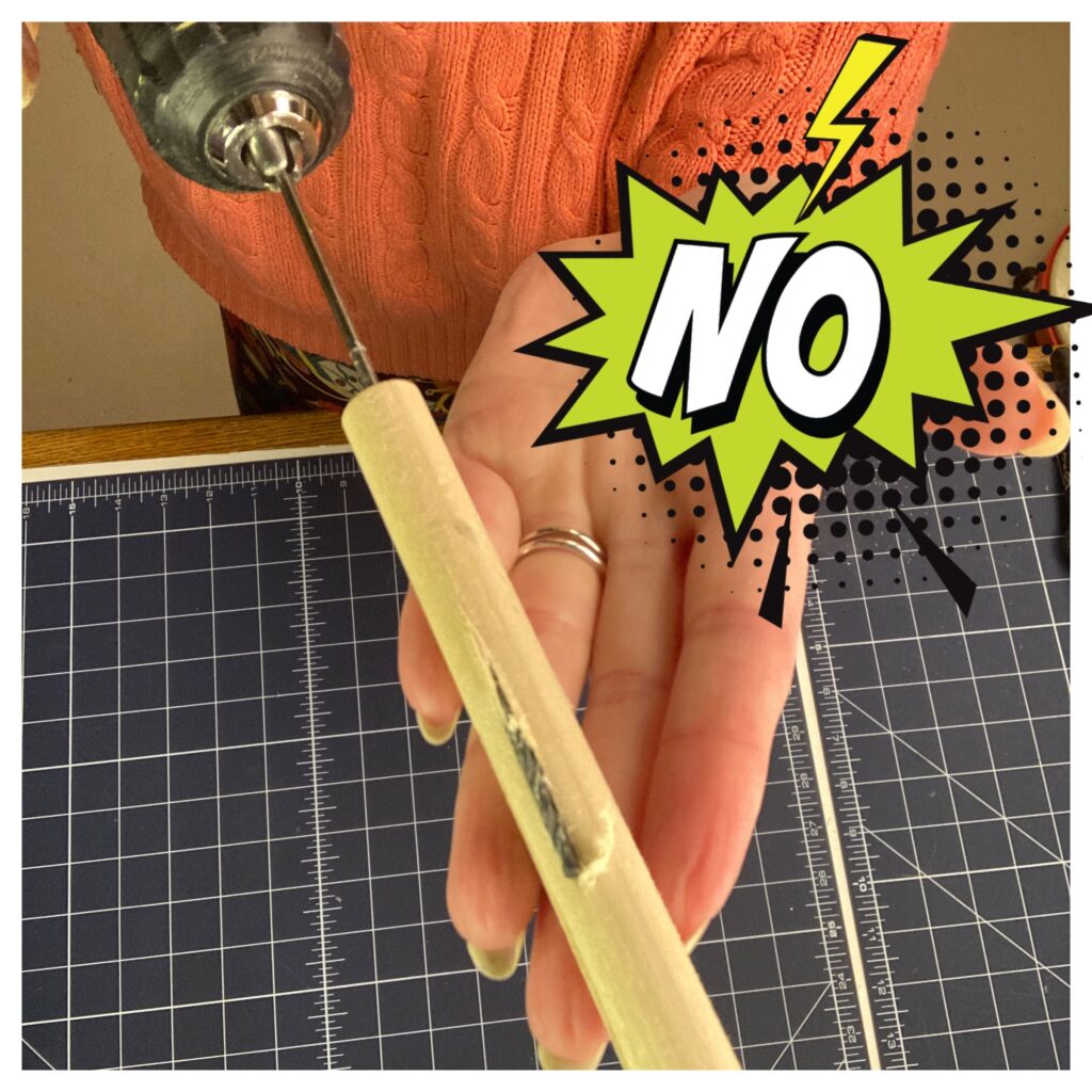
I’ve destroyed my share of dowel rods by drilling the holes for rod placement either crooked or even blowing the drill bit out the side. I didn’t have a drill press at the time, so I was eyeballing the centering of my drill bit as I drilled my holes and got terrible results.
When I learned that an offset hole would be a nice thumb rest for the puppeteer, the task was even harder on the 1/2″ dowel rod I standardly used.
Hack that By-passes the Need for a Drill Press
Since I didn’t have a drill press, I decided I needed some kind of guide that I could mount in my bench vise. To get the accuracy I needed, I designed a jig with long channels mounted above the dowel rod. This means I needed a longer drill bit, so my jig requires a 6″ long extended 3/32″ drill bit.

A 3D Printed Drill Jig – Marking and Cutting
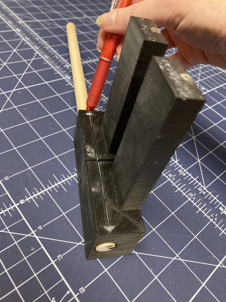
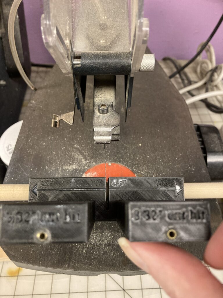
I designed my jig in Tinkercad and have the .stl files linked in this post. You have free access to the files for printing the jig parts on a 3D printer. It has two parts. A tray to load 2, 4.5″ long 1/2″ diameter dowel rods, and a snap-on guide with the drill channels (lined with brass tubing) mounted above the dowel rods. The snap-on guide also has a marking guide and dowel rod cutting jig that was not mentioned in my videos. This helps you measure and cut the dowel rod pieces before you place them in the tray. Place the 1/2″ dowel rod in the hole in the channel guide and mark your length. (See in photo below with red pen.) Push the dowel rod further into the guide until the mark shows up in the center slot. Bring the loaded channel guide to your jig saw and use it to hold the dowel rod steady for cutting at the center slot. (See image below with jig saw.) I then sand my rod ends so they are even and smooth.
A 3D Printed Drill Jig – Drilling
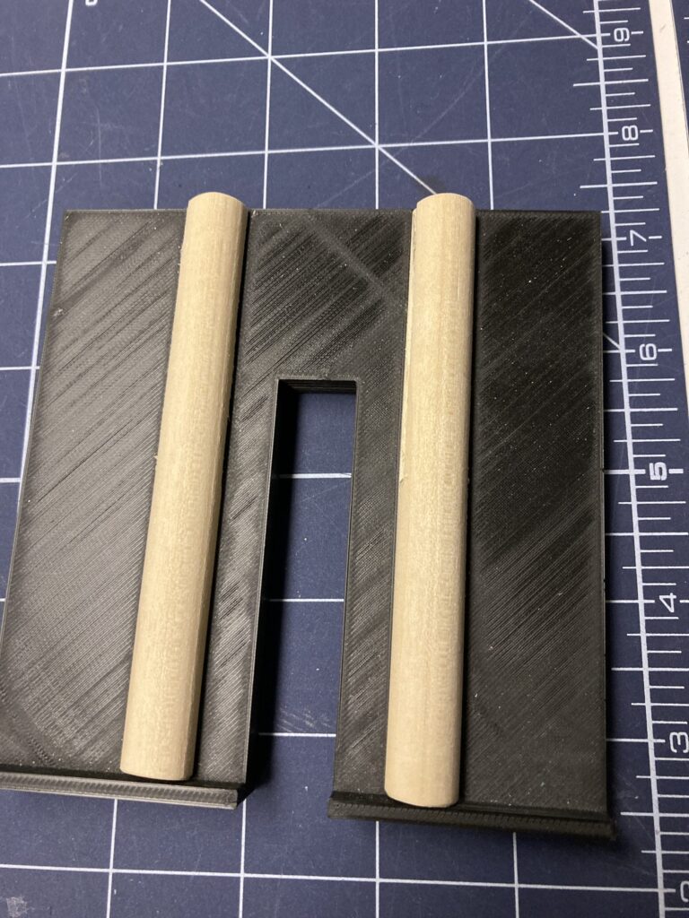
Once both rod handles are cut, place them in the tray, add the snap-on drill channel guide and mount in a bench vise with the top of the tray flush with the top of the measuring guide portion of the snap on guide. Once the jig is secure in the bench vise, use a drill fitted with a 6″ long extended 3/32″ drill bit to drill down the channels and into the dowel rods in the tray. The channels are lined with 3/32″ round brass tubing to direct the bit and prevent it from drilling into the channel guide. If you want your drilled hole deeper than the 6″ bit allows, you can remove the snap-on guide and drill directly into the dowel rod now that is has a good straight start.
If this description is confusing, please see my YouTube video:


Assembling Arm Rods
Your dowel rods are now ready for use in making your puppet’s arm rods. I notch my arm rod wire stock and sand the ends prior to using 5-minute epoxy to glue them into my freshly made dowel rod handles. The .stl files for making this jig are on my account on www.Printables.com here:
https://www.printables.com/model/610309-dowel-rod-jig-for-offset-puppet-rod-handles
More 3D Printing Files
You’ll find other puppet-related .stl files there as well. There are blog posts and videos to support how to make use of those as well;)
Note: Size specific tool
The .stl files are specific to the drill bit size and dowel rod size that I use. If you use a different size drill bit or dowel rod size, you can pull my .stl files into Tinkercad and modify them to suit your preferences. If you are unfamiliar with Tinkercad, you can use their native tutorial on how to use Tinkercad, or find other tutorials online. Once you learn Tinkercad, you will be in design idea heaven. You can dream up solutions, model them in Tinkercad, and print them. It makes your 3D printer such a valuable tool for puppet building.
Video Tutorial for the directions above:
https://www.youtube.com/shorts/TjJPVIQOToQ